CFD Supersonic Femto Logo Project
This article aims to give some insight into supersonic flows as well as the background on the STAR-CCM+ CFD simulation we performed on our own Femto Engineering logo showed below.

When thought of supersonic flows, fast fighter jets or even the Concorde comes to mind. The images of these kinds of vehicles breaking the so-called sound barrier are well known and the physics are researched thoroughly over the years. With research came the means to model and simulate supersonic flows. Nowadays, travelling faster than the speed of sound is less mysterious as it was in the 1940’s. Fueled by horror stories from fighter pilots in the second world war, various mind-blowing theories about what would happen were circulating.
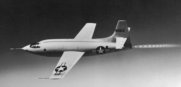
However, in 1947 the first proven successful supersonic flight ever took place. The flight was done in an experimental aircraft named the Bell X-1 piloted by the famous test pilot Chuck Yeager.
Even though most of the theories turned out to be untrue, travelling at supersonic speed still is difficult, mainly because of the significant drag penalties involved or the flight control issues that can occur. Therefore, in the years following, supersonic vehicles were mainly limited to military or experimental aircraft. With the notable exception of the famous Concorde airliner.
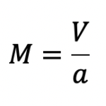
As mentioned, supersonic flows occur when the speed of the flow is faster than the (local) speed of sound α. This is typically indicated by the ratio of the two by means of the Mach number (named after Ernst Mach):
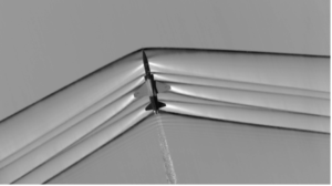
When M < 0,3 the flow is considered supersonic and shock waves are formed. These shock waves are typical for supersonic flows and are thin regions of space where flow variables such as velocity, density and pressure change very rapidly. We can visualise these shock waves by looking at the change of the density. This is the basis of the Schlieren imaging technique, invented by August Toepler in 1864. Up until recently the imaging technique was only applied in special experimental test sections until NASA Managed to apply the technique on a T-38 Talon in flight using a ground based technique.
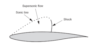
When M<0.3 the flow is subsonic. Between 0.8< M <1.2 a so-called transonic flow region exists. This is when the flow over an object can have areas locally over the surface where supersonic flow occurs. Airliners that are used for passenger flights operate typically in the transonic flow regime. Over the top side of the wing, where flow accelerates attributing to creation of lift, the local speeds can exceed the local speed of sound, causing local small shockwaves to form.
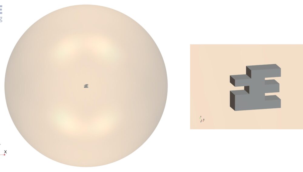
Finding the supersonic shock waves structures can done by performing CFD simulations with software such as Simcenter STAR-CCM+. For the CFD simulation around our own Femto Engineering logo, we are only interested in the shock wave patterns and therefore ignore viscous effects. This can be done by simplifying the full governing fluid flow equations (Navier-Stokes) after which the Euler equations are obtained. The free stream Mach number chosen for this simulation was M = 1.5 . The Femto logo has been modelled in 3D, placed in a 3D spherical domain, and simulated in STAR-CCM+.
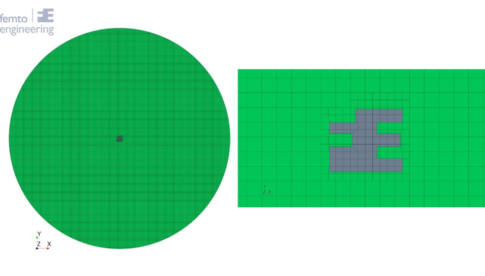
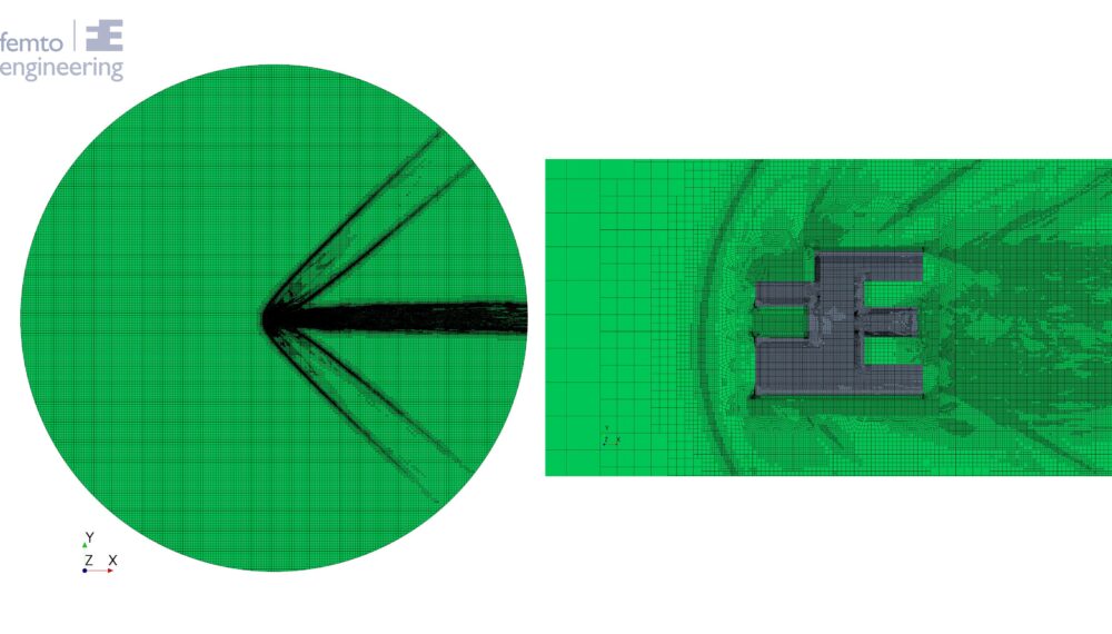
On the outer domain, the farfield boundary condition with the corresponding Mach number was used. The mesh type used is the trimmed mesh cell type. To resolve the thin shock wave structures, the automatic mesh refinement based on the density gradient was used. The mesh refinement controls can easily be customized to use any (custom) field function, which offers great flexibility. Below the geometry, initial mesh and the automatically refined mesh can be seen.
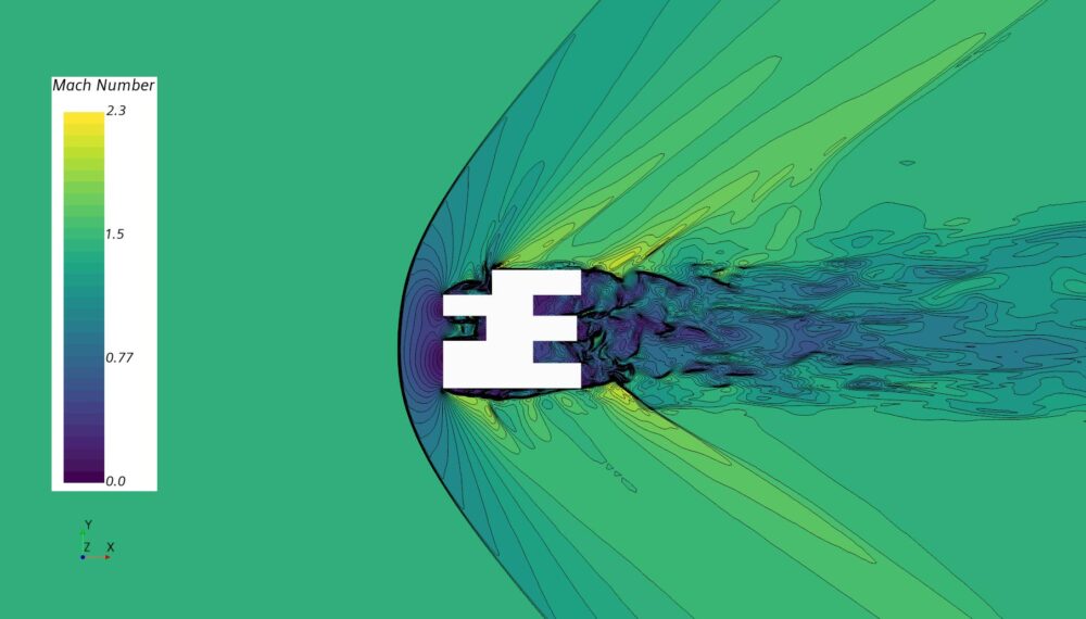
The Mach number contours around the logo show a strong shock wave in front of the logo. The Mach number after the shock wave drops to approximately M≈0.6 indicating subsonic flow. As the air flows over the edges of the Femto logo, expansion fans occur causing the Mach number to rise again, yielding supersonic flow locally.
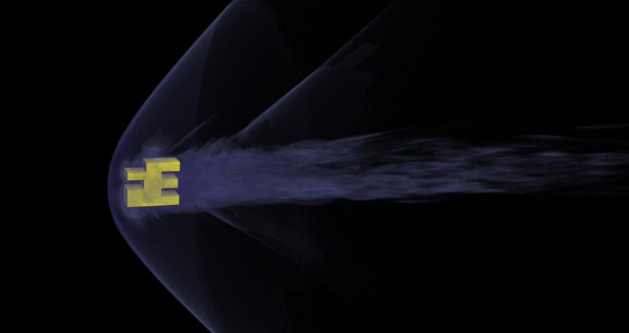
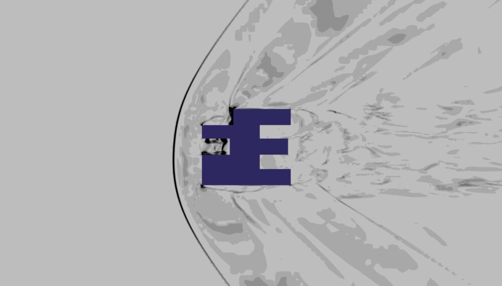
Visualizing the density gradient around the logo shows the same shock wave structure analogous to the ones that would be obtained with the Schlieren imaging technique.
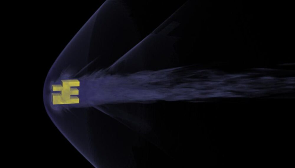
Of course, the simulation was carried out in 3D. While the results of the simulations have been shown in a midsection plane around the logo. The shock wave structures can also be visualized in 3D using the versatile volumetric rendering capabilities of STAR-CCM+. The result is shown in the figure also at the very top of this article while a slightly different angle is shown in.
To conclude, STAR-CCM+ is capable of handling a large variety of flows such as subsonic flows, multiphase flows and also including supersonic flows. A simulation of a supersonic flow around our own Femto Engineering showed that the shock wave structures can be well resolved thanks to the automatic mesh features within STAR-CCM+.
Femto Engineering is distributor for Siemens principal CFD solutions: Simcenter STAR-CCM+ in the Benelux. Our CFD engineers use the software daily in their consultancy projects and are therefore excellent sparring and support partners. Don’t hesitate to contact us!
Do you need more information or want to discuss your project? Reach out to us anytime and we’ll happily answer your questions.
At Femto Engineering we help companies achieve their innovation ambitions with engineering consultancy, software, and R&D.
We are Siemens DISW Expert Partner for Simcenter Femap, Simcenter 3D, Simcenter Amesim, Simcenter STAR-CCM+ and SDC verifier. Get in touch and let us make CAE work for you.
Sign up for our newsletter to get free resources, news and updates monthly in your inbox. Share in our expertise!