

Anti-roll tank CFD: A comparison between experiment and simulation
How can CFD simulation help engineers tune an anti-roll tank without building and testing every design iteration?

How can CFD simulation help engineers tune an anti-roll tank without building and testing every design iteration?
An anti-roll tank can reduce ship roll, but its effectiveness depends strongly on the tank’s natural frequency. In this study, we use Computational Fluid Dynamics (CFD) to investigate an anti-roll tank and compare the simulation results with experimental data from MARIN. The results show how a validated CFD model can support anti-roll tank design and help engineers evaluate design changes more efficiently.

If a ship rolls too far, it can be detrimental to the ship and/or cargo. To counteract this, an anti-roll tank can be installed. The anti-roll tank contains water that reduces the roll motion of the ship because the water in the tank moves out of phase with the ship. In this case, the water moves opposite to the motion of the tank (i.e. out of phase) and thereby exerts a force against the side of the tank that is at the highest point of the roll, thus opposing the roll motion and damping the roll.
Furthermore, the opposing moment exerted by the water is highest when the natural frequency of the tank is equal to the natural frequency of the ship. In this case, the timing of the water motion is in sync with and opposes the tank roll. Therefore, ideally, the anti-roll tank is designed so that the natural frequency of the tank is in line with the natural frequency of the ship. This allows the tank to be used under resonant conditions, where the highest roll damping is achieved.
The impact of a natural-frequency-matched anti-roll tank is shown in Figure 1 below. The peak of the anti-roll tank moment is in line with the peak of the ship roll without the anti-roll tank. The damping then results in two peaks, before and after the damping effect of the anti-roll tank, which are lower than the roll peak would have been if the anti-roll tank had not been installed.
However, the current symmetrical amplitude of the new peaks might not be ideal for a given ship. Depending on the ship and its purpose, the consequences of low- and high-frequency roll might be different.
Interested in CFD and simulation solutions for the maritime industry? Explore Femto Engineering’s maritime services!
The impact of a natural-frequency-matched anti-roll tank is shown in Figure 1 below. The peak of the anti-roll tank moment is in line with the peak of the ship roll without the anti-roll tank. The damping then results in two peaks, before and after the damping effect of the anti-roll tank, which are lower than the roll peak would have been if the anti-roll tank had not been installed.
However, the current symmetrical amplitude of the new peaks might not be ideal for a given ship. Depending on the ship and its purpose, the consequences of low- and high-frequency roll might be different.
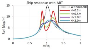
Figure 1: Result of the anti-roll tank response at different wave heights [1]
Therefore, further tuning of the anti-roll tank is an important step in the design of an anti-roll tank [1]. Reducing one peak, with the result that the other peak is increased, might be a reasonable decision for some ships. This can be achieved by tuning dimensions such as tank width, duct length, duct height, and filling height [1].
Validating each of these design iterations with physical testing would be prohibitively time-consuming. Rather than waiting for builds and tests of each iteration, or limiting the number of available iterations, anti-roll tank design can be accelerated by Computational Fluid Dynamics (CFD) simulation.
CFD can serve as a digital test environment in which the fine-tuning of an anti-roll tank design can be done quickly. Of course, sufficient agreement between experiments and the CFD model is a prerequisite. Therefore, we carried out this validation study, comparing our CFD results with the experimental results of MARIN [2] to assess the validity of a CFD-supported anti-roll tank design strategy.
Planning to optimize a design? Let us help you certify it with confidence.
In this research, a U-shaped tank is used, as shown in Figure 2, where both sides of the tank (the “legs” of the U) are referred to as wings. Once the tank begins to roll, the water will move from one of the wings to the other, causing a roll moment. When the anti-roll tank is designed correctly, the phase of the water in the tank is such that it reduces the roll motion of the ship.
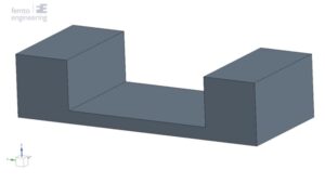
Figure 2: Geometry of the anti-roll tank
In this research, test data from MARIN, as documented in the paper Experimental data on the systematic variation of the internal damping inside a U-shaped anti-roll tank [2], is used for validation of the CFD simulation. In Figure 3, the dimensions of the anti-roll tank are shown. The tank has a width of 1 m and a height of 238 mm. The depth of the tank (in the x-direction, as per the coordinate system in Figure 3) is 416 mm. The rotation point is located in the center of the tank, 107 mm above the bottom of the tank. The water height (black dashed line) is 119 mm above the bottom of the tank. The water density is 1000 kg/m³.
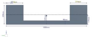
Figure 3: Dimensions of the anti-roll tank
For this validation, a roll angle amplitude of 1° was used, with a range of angular frequencies between 1.07 and 3.22 rad/s.
In the CFD analysis, a Volume of Fluid (VOF) model was used in combination with automatic mesh refinement (AMR) and an adaptive time step (ATS). A forced input roll motion was given to the tank, with the point of rotation placed as shown in Figure 2. This is also the location where the moment around the x-axis is measured.
In the experiments performed by MARIN, a roll damping coefficient, Bx (in N·m·s/rad), is used to document the results [1].
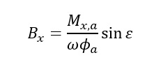
In this equation M x,a is the moment around the x-axis for experiment a, ω is the corresponding angular frequency, ɸα is the roll angle and ɛ is the phase change. The phase change is the shift in phase of the forced roll compared to the moment response.
In this equation is the mIn this equation is the moment around the x-axis for experiment a, is the corresponding angular frequency, is the roll angle and is the phase change. The phase change is the shift in phase of the forced roll compared to the moment response. oment around the x-axis for experiment a, is the corresponding angular frequency, is the roll angle and is the phase change. The phase change is the shift in phase of the forced roll compared to the moment response.
MARIN calculated the roll damping coefficient based on the experimental results for moment amplitude and phase angle [2]. In Figure 3, these results are compared with the calculated damping coefficient based on the moment amplitude and phase angle resulting from the CFD simulations. Overall, a good match is found using the CFD analysis, with a coefficient of determination (R²) of 0.98.
Initially, the simulation predicts the roll damping coefficient quite well, with errors under 5%. At an angular frequency of 2.25 rad/s, however, the CFD simulation slightly overpredicts the roll damping coefficient, with errors of up to 15%. These errors decrease when approaching the peak (<5%). The peak of the CFD simulations is predicted about 0.1 rad/s lower than the peak of the experiments. The simulated peak roll damping coefficient value is still very close, with only a 2% difference from the experimental value at the same angular frequency. On the other hand, the experimental and simulated peak values differ by 11% in roll damping coefficient and 0.1 rad/s in angular frequency.
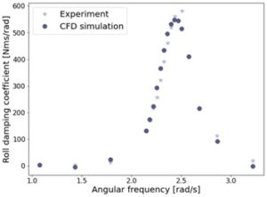
Figure 4: Experimental results [1] compared to the CFD results
The roll damping coefficient is dependent on both the maximum moment value and the phase angle. In Figures 5 and 6, the phase angle and moment amplitude for the CFD simulations at all angular frequencies are shown. The phase angle shows the expected curve, as can also be found in the literature [2]. Only the phase angle at an angular frequency of 2.86 rad/s is slightly off from the curve. If the phase angle were the reason for the differing peak location of the roll damping coefficient, it would be expected that the curve would show incorrect behaviour around 2.4 rad/s, since the roll damping coefficients before this value are close to the experimental values.
Since this is not the case, it is expected that the moment amplitude is the reason for the lower peak location of the roll damping coefficient. This is also visible in Figure 6, where the moment amplitude shows the same curve as the roll damping coefficient.
This would mean that the amplitude of the water levels is lower than in the experiments at the peak angular frequencies, causing a lower moment amplitude in these regions as well. The CFD simulation therefore shows more damping, which leads to a lower roll damping coefficient than in the experiment.

Figure 5: Phase angle
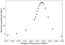
Figure 6: Moment amplitude
The results match quite well with the experimental results, with a coefficient of determination of 0.98. The simulation results show a slightly lower roll damping coefficient at lower angular frequencies and a slightly higher roll damping coefficient at higher angular frequencies. Only the peak roll damping coefficient is predicted at a 0.1 rad/s lower angular frequency (2.43 rad/s versus 2.50 rad/s). The lower peak location is due to a lower amplitude of the water height at the peak roll damping coefficient, and therefore a lower moment amplitude. The simulated phase change angles are close to the expected values when looking at similar experimental curves [2]. At an angular frequency of 2.86 rad/s, the simulated value deviates from the behaviour of the expected curve.
However, this is the only value that does this; all other values follow the expected curve. Since the phase change angle shows the expected behaviour, and the curve does not show a divergence from the expected behaviour around the peak of the roll damping coefficient, it is expected that the moment amplitude is the reason for the difference in the roll damping coefficient peak location.
CFD analysis matches quite well with the experimental results, with a coefficient of determination of 0.98. The predicted peak damping is at a slightly lower frequency than expected, and the roll damping is also lower than expected. This means that the ship roll will be damped slightly less than was observed experimentally. This slight underestimation represents a conservative method, because greater damping in practice would be considered a performance and safety improvement.
Hence, the current CFD methods are well-suited for accelerating anti-roll tank (ART) design and validation. This is especially relevant when designing a U-shaped tank, where the natural frequency depends on a variety of dimensions, including width, length, duct height, and filling height. CFD analysis can make the process from first design to final design much faster.
This validation shows that CFD can be a practical tool for anti-roll tank design, from early concept development to final tuning. As a CAE consultancy, Femto Engineering helps engineering teams make use of Simcenter STAR-CCM+ and other Simcenter simulation softwares to investigate complex fluid dynamics, validate simulation models against test data, and optimize designs before committing to physical prototypes.
If you are developing an anti-roll tank or facing a similar fluid-dynamics challenge, our CFD engineers can help you assess the right simulation approach and identify opportunities for faster design iterations. Book a free intake with Femto Engineering to discuss your project.
Author: Frouke Kruijssen
CFD Simulation Engineer, Femto Engineering
[1] N. Carette, R. P. Dallinga and G. K. Kapsenberg, “On the design of anti-roll tanks,” in PRADS2016, Copenhagen, Denmark, 2016.
[2] M. Gunsing, N. Carette and G. Kapsenberg, “Experimental Data on the Systematic Variation of the Internal Damping Inside a U-shaped Anti-Roll Tank,” in ASME 2014 33rd International Conference on Ocean, Offshore and Arctic Engineering, San Fransisco, 2014.
[3] S. Field and J. martin, “Comparative effects of U-tube and Free Surface type passive roll stabilisations systems,” Trans. RINA, 1976.
Do you need more information or want to discuss your project? Reach out to us anytime and we’ll happily answer your questions.
At Femto Engineering we help companies achieve their innovation ambitions with engineering consultancy, software, and R&D.
We are Siemens DISW Expert Partner for Simcenter Femap, Simcenter 3D, Simcenter Amesim, Simcenter STAR-CCM+, SDC verifier, Altair HyperWorks, Altair SimSolid and Altair PhysicsAI. Get in touch and let us make CAE work for you.
Sign up for our newsletter to get free resources, news and updates monthly in your inbox. Share in our expertise!