Biplanes: Why did they disappear? - Femto Engineering - Femto Engineering

Biplanes: Why did they disappear?

Using CFD aerospace simulation in Simcenter STAR-CCM+, this article compares biplane and monoplane aerodynamic performance, explaining how improved wing efficiency and reduced drag led to the disappearance of biplanes.

History of the Biplane

At the very dawn of aviation, planes looked different than they do now. They were typically lightweight, made of wood and cloth, often launched by manpower or a rail, needing only a support structure to land, which is why we still call it “landing gear”

One of the features that mostly disappeared over time is planes with multiple wings above one another. These were essential for generating enough lift, while working within the material structural constraints of the early aviation industry.

Figure 1 Airwolfhound from Hertfordshire, UK – Sopwith Camel – Season Premiere Airshow 2018 (CC BY 2.0)

But why do we barely see these anymore?

The most important reason is that with the wood and cloth wings, longer and more slender wings were structurally unfeasible. As material sciences improved, and new, lightweight building methods where developed wings became longer, which generated more lift and reduced drag (for a given wing area).

Figure 2 Tony Hisgett from Birmingham, UK – Sopwith Triplane 3 (CC BY 2.0)

CFD analysis of Biplane vs Monoplane configurations

Work performed

In this article, we analyse the aerodynamic forces on the wings of a toy plane (see Figure 3), comparing three different wing geometries:

  •  a single rectangular wing
  • the same wing geometry, but as a biplane
  • a longer single rectangular wing

Figure 3: Toy Plane used

For our longer wing, we chose it such that the lift was approximately equal to the lift generated by the biplane.

Planning to optimize a design? Let us help you certify it with confidence.

Talk to our expert

Modelling

These planes are simulated in Simcenter STAR-CCM+ using steady state modelling. By simulating the airflow around our toy plane, we can determine the lift and drag of the different configurations

For our toy plane wing, a NACA 2415 wing was selected. The wing was given an initial angle of attack of 2 degrees.

Results

The lift and drag for the different wing configurations are listed in the table below:

This shows that doubling the wings for lift is a good practice as it more than doubles the lift, but that the drag is doubled as well.

It also shows that it isn’t necessary to double the wing length to double the lift, which is one of the reasons that the elongated wing has a better lift-to-drag ratio than the biplane.

Why does this happen though?

Most of the answer lies in the wingtips. Wings generate lift by the pressure difference on the top and bottom of the wings. At the wing tips, rather than following the flow around the wing’s profile, the air goes over the tips, which reduces the pressure difference between the top and bottom of the wing in the region near the tip, thus reducing the lift. This can be seen in Figure 4 for both the original wing and the longer wing. These wing tip vortex losses are present in all wings (although modern planes reduce these by adding winglets), however they are more pronounced in shorter wings.

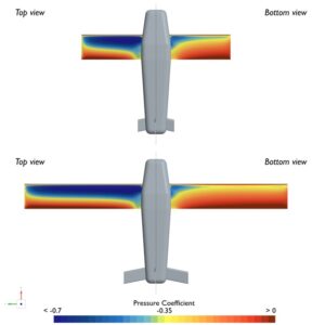
Figure 4: Pressure coefficient Top and Bottom for both the original and longer wing

The lift force distribution over the wings is shown for the three configurations in Figure 5. The effect of the fuselage and wingtips on the wings is clearly visible.

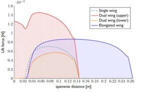
Figure 5: Spanwise Lift distributions for the three configurations

Figure 7 to Figure 9 shows the pressure distribution for the different simulations, taken at different spanwise sections of the wing (see Figure 6).

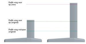
Figure 6: Section locations for the original and elongated wing


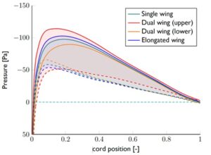
Figure 7: Pressure profiles mid span for the different wings

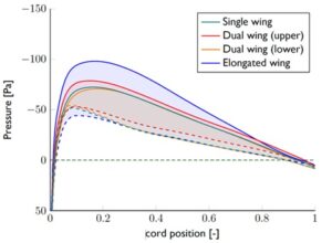
Figure 8 Pressure profiles at the original wing tip location for the different wings


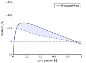
Figure 9 Pressure profiles at the elongated wing tip location

Discussion

No additional wing components, nor struts and cables have been included, but these would adversely affect the biplane configuration, adding significant drag to this version that is not present in the other models. There are also some interesting effects, such as the flow acceleration over the fuselage, which increases the lift of the centre section of the top wing, as shown in Figure 10.

Figure 10: Velocity field on the symmetry plane for both double and single wing

This acceleration effect also has an influence on the wings themselves, where it disturbs the velocity field, leading in a slightly lower performance for the lower wing. Many bi- and triplanes (like the triplane in Figure 2) had staggered wings for this very reason (forward since this has better handling characteristics when manouevering.

Conclusion

This CFD-based aerospace simulation highlights why biplanes gradually disappeared from mainstream aviation design.

While multiple wings can effectively increase lift, longer single wings provide better aerodynamic efficiency by reducing drag and minimising wingtip losses. Advances in structural materials and manufacturing enabled aircraft designers to transition toward high-aspect-ratio monoplane wings, which dominate modern aviation today.

Using CFD tools such as Simcenter STAR-CCM+ allows engineers to visualise these aerodynamic effects in detail and better understand the evolution of aircraft wing design.

Planning to optimize a design? Let us help you certify it with confidence.

Talk to our expert

May 21, 2026
get in touch

Do you need more information or want to discuss your project? Reach out to us anytime and we’ll happily answer your questions.

about us

At Femto Engineering we help companies achieve their innovation ambitions with engineering consultancy, software, and R&D.
We are Siemens DISW Expert Partner for Simcenter Femap, Simcenter 3D, Simcenter Amesim, Simcenter STAR-CCM+SDC verifier, Altair HyperWorks, Altair SimSolid and Altair PhysicsAI. Get in touch and let us make CAE work for you.

Privacy policy

×

Be ahead in FEA & CFD

Sign up for our newsletter to get free resources, news and updates monthly in your inbox. Share in our expertise!