Validating fundamentals: 2D NACA 0012 Airfoil Validation - Femto Engineering - Femto Engineering

Validating fundamentals: 2D NACA 0012 Airfoil Validation

In Computational Fluid Dynamics (CFD) we can simulate a lot of different cases, from single-phase internal or external pipe flows to complicated cases including multiple phases, heat, radiation, and DEM particles. In this series we are going back to some validation cases.

In this article we will validate a 2D NACA 0012 Airfoil case. The case is based on the validation case setup by NASA [1][2]. The case consists of a NACA 0012 airfoil in a far-field domain and a Mach 0.15 airflow.

Geomeetry and mesh

The NACA 0012 airfoil is defined according to the following equation [1]:


y=-0.594689181[0.298222773√x-0.127125232x-0.357907906x^2+0.291984971x^3-0.105174606x^4 ]


The airfoil is defined in such a way that the chord of the airfoil is exactly 1m long, starting at x = 0 and ending at x = 1.

A far-field domain is created around the airfoil, where the maximum dimensions of the domain are all 500m. The airfoil is located in the middle of the domain, but is not visible in the image below due to its size compared to the domain.

An unstructured mesh is created in the domain, where the mesh is refined around the airfoil and in the wake of the airfoil. Prism layers are added to the airfoil, such that the y+ on the airfoil wall is lower than 1.

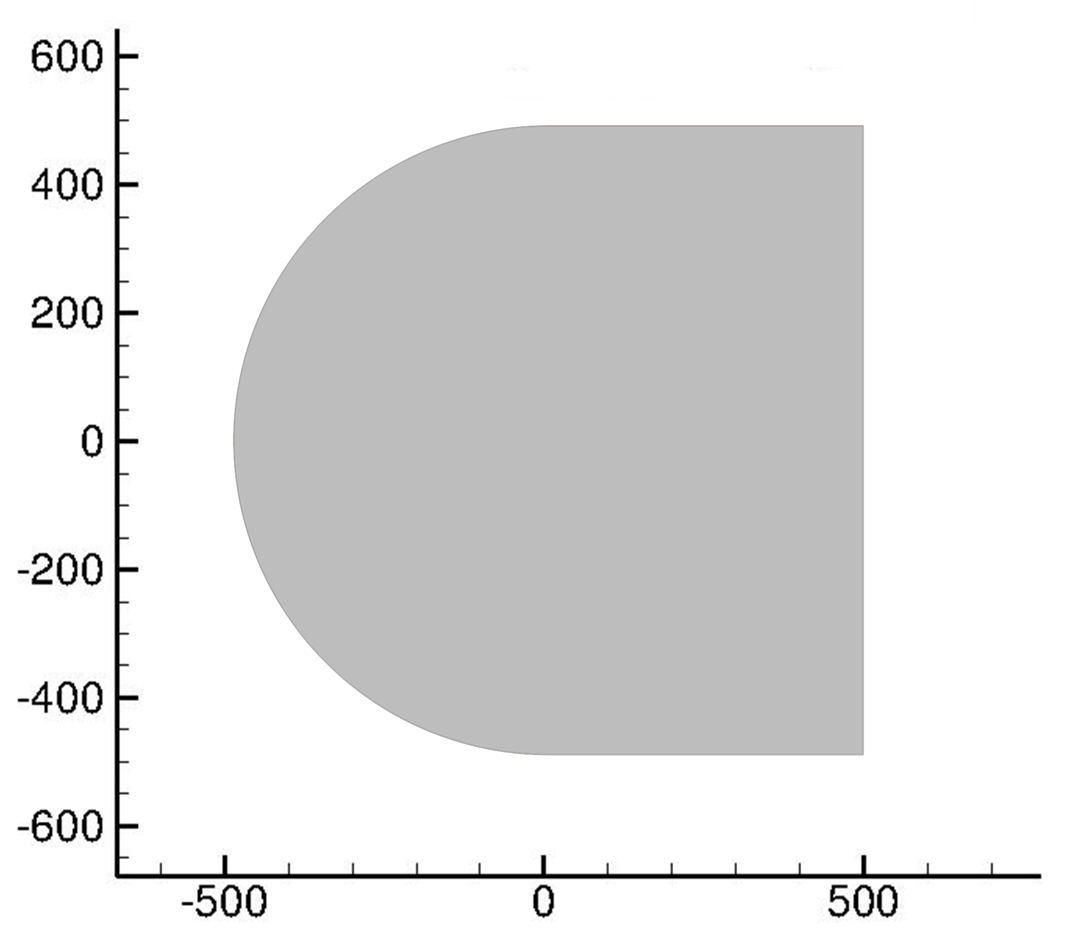
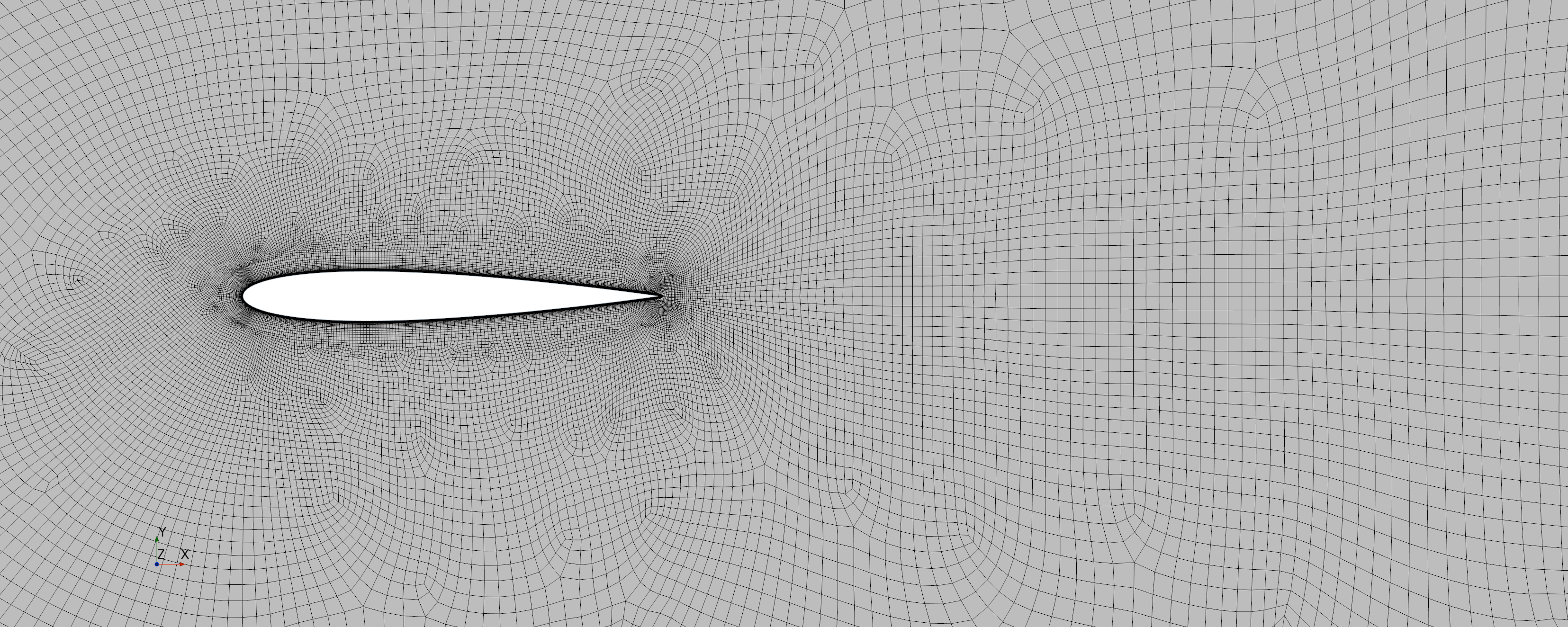
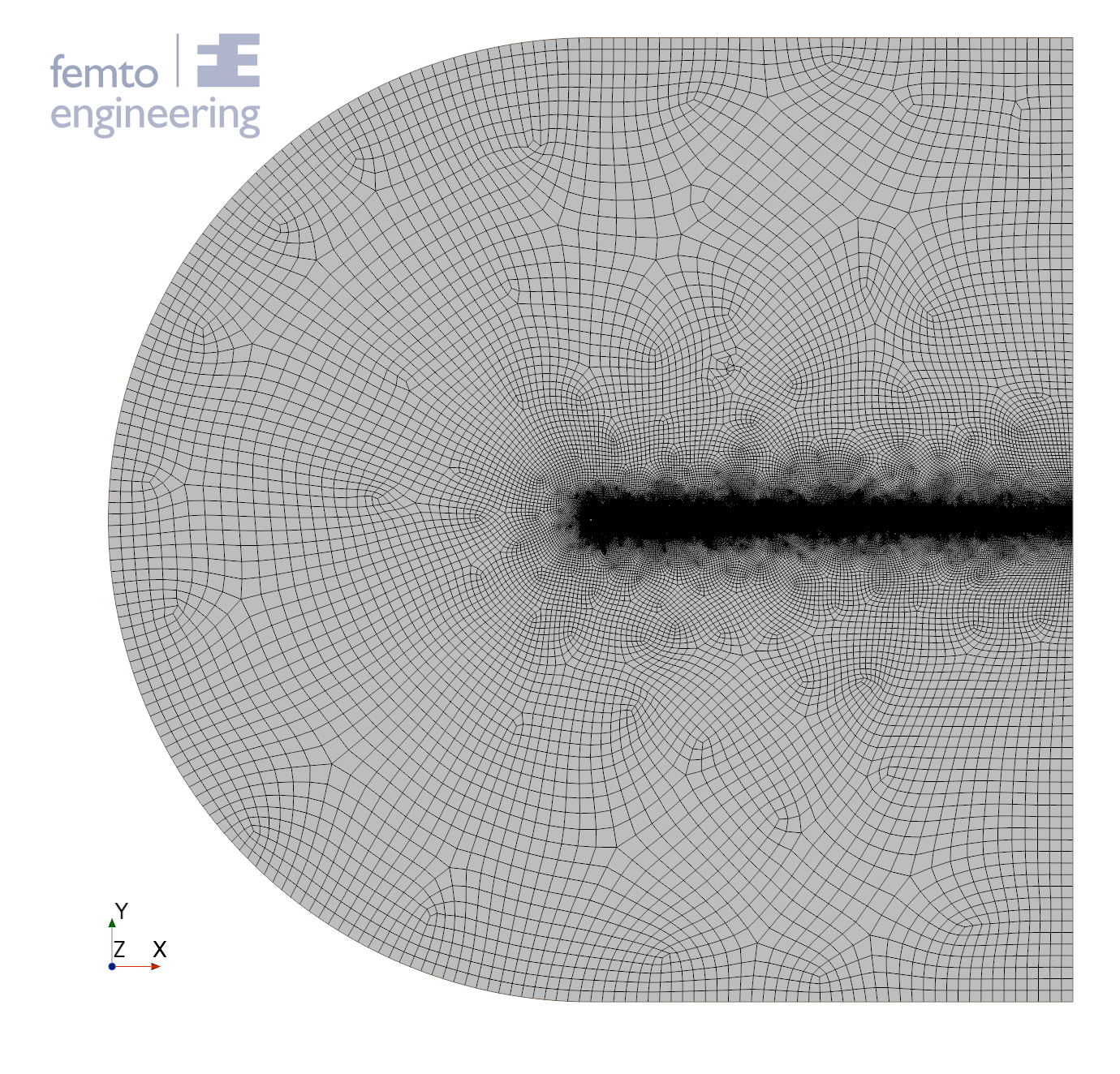
Figure 1: mesh and domain


Figure 2: mesh around the airfoil

Setup

A compressible simulation is set up using the Spalart-Allmaras RANS turbulence model with the fluid modelled as an ideal gas. The used settings are summarized below. The pressure is such that the Reynolds number is exactly 6 million with a Mach number of 0.15 and a chord length of 1.

Variable

Value

Unit

Temperature

300

K

Mach number

0.15

Chord length

1

M

Reynolds number

6E6

Dynamic Viscosity

1.85E-5

Pa-s

Pressure

183133

Pa

Results

The results are compared to NACA 0012 airfoil experiments performed by C.L. Ladson [3][4] and the experiments performed by I.H. Abbott and A.E. von Doenhoff [5]. These experiments are performed at a Reynolds number of 6 million. The experiments done by C.L. Ladson were tripped, which means that the flow over the airfoil moves over a ridge to force separation. The results are also compared to the experiments performed by N. Gregory and C.L. O’Reilly [6], which were performed at a Reynolds number of 3 million and were tripped as well.

Figure 3: cl-cd plot

figure 4: Cl-angle plot

From the drag versus lift coefficient (Cd-Cl) plot and the lift coefficient versus angle (Cl-angle) plot it can be concluded that a relatively good comparison can be drawn between the experimental results and the simulations. However, around the point of separation (angle of 11˚) the resulting lift and drag forces found with the simulation are no longer in line with the experimental results.
However, it can be concluded from the pressure distribution over the airfoil, that the pressure distribution gives a good comparison compared with the experimental results all the way up to an angle of 15˚. Note that no comparison has been made for angles above 15˚.


Figure 5:  Pressure distribution over the airfoil at different angles

Conclusions

In conclusion, Simcenter StarCCM+ provides a good comparison between the experimental results of the forces on a NACA 0012 airfoil and the simulation results using the Spalart-Allmaras model.

References

[1] https://turbmodels.larc.nasa.gov/naca0012_val.html
[2] https://turbmodels.larc.nasa.gov/naca0012numerics_val.html
[3] Ladson, C. L., “Effects of Independent Variation of Mach and Reynolds Numbers on the Low-Speed Aerodynamic Characteristics of the NACA 0012 Airfoil Section,” NASA TM 4074, October 1988
[4] Ladson, C. L., Hill, A. S., and Johnson, Jr., W. G., “Pressure Distributions from High Reynolds Number Transonic Tests of an NACA 0012 Airfoil in the Langley 0.3-Meter Transonic Cryogenic Tunnel,” NASA TM 100526, December 1987
[5] Abbott, I. H. and von Doenhoff, A. E., “Theory of Wing Sections,” Dover Publications, New York, 1959
[5] Gregory, N. and O’Reilly, C. L., “Low-Speed Aerodynamic Characteristics of NACA 0012 Aerofoil Sections, including the Effects of Upper-Surface Roughness Simulation Hoar Frost,” R&M 3726, Jan 1970

May 23, 2022
get in touch

Do you need more information or want to discuss your project? Reach out to us anytime and we’ll happily answer your questions.

about us

At Femto Engineering we help companies achieve their innovation ambitions with engineering consultancy, software, and R&D.
We are Siemens DISW Expert Partner for Simcenter Femap, Simcenter 3D, Simcenter Amesim, Simcenter STAR-CCM+ and SDC verifier. Get in touch and let us make CAE work for you.

Privacy policy

×

Be ahead in FEA & CFD

Sign up for our newsletter to get free resources, news and updates monthly in your inbox. Share in our expertise!